Copper Machined Parts: What Precision Can They Achieve? How to Control Processing Costs When Customizing?
2025-10-31
Content
- 1 1. What Precision Ranges Can Copper Machined Parts Reach? It Depends on Processing Technology
- 2 2. What Factors Affect the Precision of Copper Machined Parts? Don’t Ignore These Details
- 3 3. How to Control the Processing Cost of Custom Copper Machined Parts? Start with Design Optimization
- 4 4. How to Reduce Costs Through Processing Technology Selection and Batch Optimization?
- 5 5. What Common Cost Pitfalls Should Be Avoided When Customizing Copper Machined Parts?
1. What Precision Ranges Can Copper Machined Parts Reach? It Depends on Processing Technology
The precision of copper machined parts is not fixed; it varies significantly with the choice of processing technology, as different technologies have distinct capabilities in controlling dimensional accuracy and surface quality. For conventional processing methods, such as turning and milling (using ordinary CNC machines), the dimensional accuracy of copper parts is usually between ±0.01mm and ±0.1mm. For example, when processing a copper shaft with a diameter of 20mm via ordinary CNC turning, the final diameter error can be controlled within ±0.03mm, which meets the needs of most general industrial scenarios (such as ordinary connectors and low-pressure valves).
For high-precision processing scenarios, technologies like precision turning, grinding, and electrical discharge machining (EDM) can push the precision to a higher level. Precision CNC turning (equipped with high-precision spindles and linear guides) can achieve dimensional accuracy of ±0.005mm to ±0.01mm, and the surface roughness (Ra) can be reduced to 0.2μm to 0.8μm—this is suitable for parts requiring tight fits, such as precision bearings and hydraulic valve cores. Grinding processing (especially external cylindrical grinding) performs even better: for copper parts with a smooth surface, the dimensional accuracy can reach ±0.001mm to ±0.003mm, and the surface roughness can be as low as 0.025μm (close to mirror effect), which is often used in high-precision instruments (like sensor components).
EDM, which uses electrical erosion to shape parts, is suitable for complex copper structures (such as parts with fine holes or narrow slots) that are difficult to process with traditional cutting methods. Its dimensional accuracy is generally between ±0.002mm and ±0.005mm, and it can process microstructures with a minimum width of 0.1mm, making it ideal for precision molds and microelectronic components. However, it should be noted that the precision of EDM is affected by the electrode wear, so additional compensation measures are needed during processing to ensure accuracy.
2. What Factors Affect the Precision of Copper Machined Parts? Don’t Ignore These Details
Even with the same processing technology, the final precision of copper machined parts may be compromised by multiple factors, which need to be paid attention to during the processing process. The first key factor is the "thermal deformation of copper materials". Copper has a high thermal conductivity (about 401W/(m·K), much higher than steel’s 50W/(m·K)), but its coefficient of thermal expansion is also relatively large (16.5×10^-6/℃). During cutting, the friction between the tool and the copper part generates heat, which causes the copper part to expand. If the heat is not dissipated in time, the processed size will be smaller than the design size after the part cools down. For example, when processing a copper plate with a length of 100mm, if the cutting temperature rises by 50℃, the thermal expansion of the copper plate will be about 0.0825mm. If this is not considered in the processing parameters, the final length error may exceed the allowable range.
The second factor is "tool wear and selection". Copper is a relatively soft material (Brinell hardness is about 35HB to 100HB, depending on the type), so the tool is prone to "built-up edge" during cutting—copper chips adhere to the tool tip, changing the actual cutting edge shape and leading to dimensional errors. To avoid this, it is necessary to select tools with high wear resistance and appropriate coatings. For example, carbide tools coated with titanium nitride (TiN) have good wear resistance and can reduce built-up edge; for high-precision processing, diamond tools (with extremely high hardness and smooth surface) are more suitable, as they can minimize tool wear and ensure stable processing precision.
The third factor is "fixture stability and clamping force". If the fixture used to fix the copper part is loose or the clamping force is uneven, the part will shift during processing, resulting in dimensional deviation. For example, when clamping a thin copper sheet for milling, excessive clamping force will cause the sheet to deform (buckling or warping), and after processing and unloading, the sheet will rebound, making the processed shape inconsistent with the design. Therefore, it is necessary to use fixtures with good rigidity (such as vacuum chucks for thin sheets) and adjust the clamping force according to the thickness and shape of the copper part—generally, the clamping force should be just enough to prevent the part from moving without causing obvious deformation.
3. How to Control the Processing Cost of Custom Copper Machined Parts? Start with Design Optimization
Design is the first link affecting the cost of custom copper machined parts. Reasonable design can reduce processing difficulty and material waste, thereby lowering costs. The first design principle is "simplifying the part structure". Complex structures (such as deep holes, blind holes, or irregular curved surfaces) require more processing steps and longer processing time, which directly increases costs. For example, a copper part with a 10mm-diameter, 50mm-deep blind hole requires multiple tool changes and chip removal operations during drilling, and the processing time is 3-5 times that of a through hole of the same diameter. If the design allows, changing the blind hole to a through hole or reducing the depth of the blind hole can significantly shorten the processing cycle and reduce costs.
The second principle is "unifying processing datums and reducing tool changes". During processing, each tool change requires time for tool setting and calibration, and frequent tool changes will increase the processing time and the risk of precision errors. Therefore, in the design, it is necessary to try to unify the processing datums (such as using the same end face or axis as the datum for multiple processing features) and select processing features that can be completed with the same tool. For example, if a copper part needs to process two steps with different diameters, designing the steps to have the same taper (so that they can be processed with a single tapered tool) can avoid tool changes and save 20%-30% of the processing time.
The third principle is "reasonably setting precision requirements". Excessively high precision will force the use of more advanced processing technologies and longer processing times, leading to cost increases. For example, if a copper part used in a general pipe joint only needs a dimensional accuracy of ±0.1mm, but the design requires ±0.005mm, the processing cost may increase by 5-10 times (since it needs to switch from ordinary CNC turning to precision grinding). Therefore, during design, it is necessary to "match precision to usage scenarios": for non-critical features (such as non-fitting surfaces), appropriately relax the precision requirements (such as increasing the dimensional tolerance to ±0.1mm-±0.2mm) without affecting the overall performance of the part.
4. How to Reduce Costs Through Processing Technology Selection and Batch Optimization?
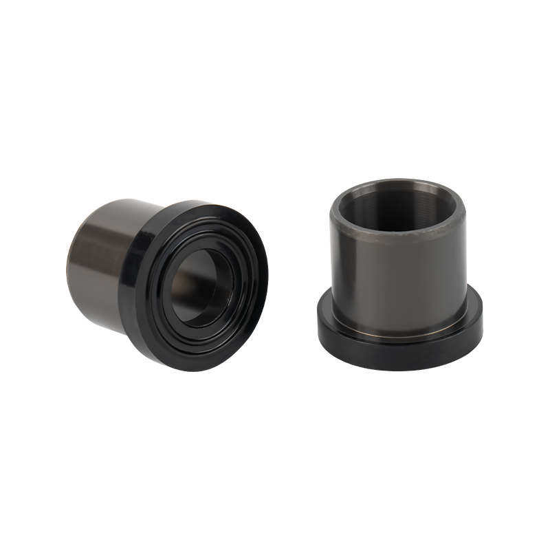
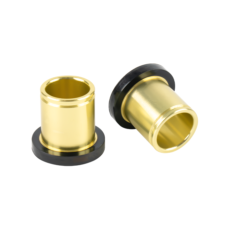
After confirming the design, selecting the right processing technology and optimizing the production batch are also key to controlling the cost of copper machined parts. The first aspect is "selecting cost-effective processing technologies based on batch size". For small-batch customization (usually 1-50 pieces), it is more economical to use CNC turning or milling, as these technologies have short setup times and do not require expensive molds. For example, processing 10 copper bushings via CNC turning only takes 2-3 hours for setup and processing, and the unit cost is about 10-20. However, for large-batch production (1000 pieces or more), technologies like die casting or extrusion (followed by simple machining) are more cost-effective. Die casting can produce copper parts in batches quickly (each mold can produce multiple parts at once), and the unit cost can be reduced to 3-5—this is suitable for standardized parts (such as copper nuts and connectors).
The second aspect is "optimizing processing parameters to improve efficiency". Reasonable adjustment of cutting speed, feed rate, and depth of cut can shorten the processing time while ensuring precision. For example, when processing pure copper (with good ductility) via CNC turning, increasing the cutting speed from 100m/min to 300m/min (using a carbide tool) can reduce the cutting time per part by 40%-50% without affecting the surface quality. However, it should be noted that the cutting parameters should match the tool and machine tool capabilities—excessively high cutting speed may accelerate tool wear and increase tool replacement costs, so a balance needs to be found.
The third aspect is "reducing material waste through nesting optimization". Copper materials are relatively expensive (the price of pure copper is about 8-10 per kg), so reducing material waste is crucial for cost control. For sheet-like copper parts, nesting software can be used to arrange the part shapes on the copper sheet as tightly as possible to maximize the utilization rate of the material. For example, when processing a copper washer with a diameter of 15mm, nesting optimization can increase the number of washers processed per 100mm×100mm copper sheet from 40 to 50, reducing material waste by 20%. For bar-like parts, selecting the appropriate bar diameter (to avoid excessive leftover material) is also important—for example, processing a copper shaft with a diameter of 18mm should use a 20mm-diameter bar instead of a 25mm-diameter bar, as the latter will generate more leftover material.
5. What Common Cost Pitfalls Should Be Avoided When Customizing Copper Machined Parts?
In the process of customizing copper machined parts, some misunderstandings or oversights may lead to unnecessary cost increases, which need to be avoided. The first common pitfall is "unclear technical requirements leading to rework". If the design drawings do not clearly specify key parameters (such as dimensional tolerances, surface roughness, and material grades), the processing factory may process the parts according to default standards, which may not meet the actual needs and require rework. For example, if the drawing does not specify the surface roughness of a copper part, the factory may process it to Ra 3.2μm (ordinary standard), but if the actual need is Ra 0.8μm, the part will need to be re-ground, increasing the cost by 30%-50%. Therefore, the design drawings must clearly mark all technical requirements, and communicate with the processing factory in advance to confirm the feasibility.
The second pitfall is "ignoring the cost of post-processing". Many copper parts require post-processing (such as plating, heat treatment, or deburring) to meet performance or appearance requirements, and these processes also account for a certain proportion of the total cost. For example, electroplating a copper part with a nickel layer (to improve corrosion resistance) adds about 1-3 per part, and heat treatment (such as annealing to reduce internal stress) adds 2-5 per part. If these costs are not considered in the early stage, the final total cost may exceed the budget. Therefore, when customizing, it is necessary to list all required post-processing steps and obtain quotations from the processing factory in advance, and optimize the post-processing plan if possible (such as using passivation instead of plating for non-corrosive environments to reduce costs).
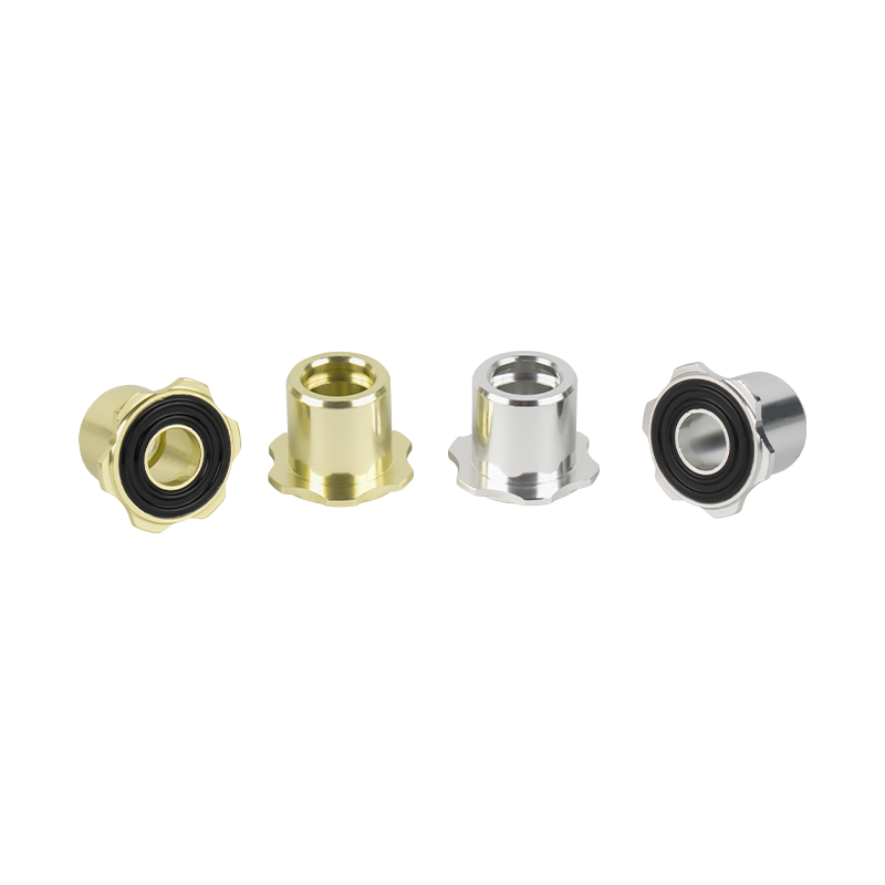
The third pitfall is "choosing the wrong processing factory". Different processing factories have different strengths (such as some are good at precision processing, while others are good at large-batch production) and pricing strategies. Choosing a factory that does not match the customization needs may lead to high costs or low precision. For example, if you need to customize 10 high-precision copper parts, choosing a factory that mainly focuses on large-batch low-precision processing may result in the factory using expensive high-precision equipment (which is not fully utilized) and charging higher fees. Instead, choosing a small and medium-sized factory specializing in precision processing can get more reasonable prices and better quality. Therefore, it is necessary to screen processing factories based on factors such as batch size, precision requirements, and technical capabilities, and compare multiple quotations before making a decision.

 English
 русский
 中文简体
中文简体