

 English
 русский
 中文简体
How Does an Engine Work? Four-Stroke Cycle and Key Parts Explained Simply
2026-10-26
Content
- 1 The Four-Stroke Cycle, Step by Step
- 2 Core Components That Make the Cycle Possible
- 3 Valve Timing: Precision That Shapes Performance
- 4 Where Torque Goes After the Power Stroke
- 5 Common Failures and What They Signal
- 6 Electrified Valve Control: Solenoids in Engine and Air Systems
- 7 What Keeps an Engine Reliable Over Time
A heavy truck pulls onto an uphill grade with a full trailer. The driver opens the throttle, engine speed settles at 1,800 rpm, and each cylinder fires 900 times a minute. Inside every one of those firings, the same four-step sequence repeats: intake, compression, power, exhaust. This article explains what happens at each step, which components carry it out, and why the same sealing discipline that governs engine valves also governs the pneumatic valves around a commercial vehicle.
The Four-Stroke Cycle, Step by Step
Nearly every piston engine in cars and commercial trucks runs on the four-stroke principle. One complete cycle produces a single power stroke and requires two full turns of the crankshaft. The name of each stroke describes exactly what the piston does during that phase.
- Intake. The piston descends while the intake valve is open, drawing air — and fuel, in port-injected gasoline engines — through the intake manifold into the cylinder.
- Compression. Both valves close. The piston rises and squeezes the charge into a small fraction of its original volume. In a diesel engine, that compression alone heats the air enough to ignite fuel sprayed in at the end of this stroke.
- Power. The charge ignites and combustion gases expand violently, pushing the piston downward with considerable force. This is the only stroke that transfers energy to the crankshaft; all engine torque comes from this phase.
- Exhaust. The exhaust valve opens and the rising piston pushes the burned gases out through the exhaust manifold, leaving the cylinder ready for the next intake stroke.
Three of the four strokes consume energy. That is why the crankshaft carries a flywheel: rotational inertia bridges the gap between power strokes and keeps the engine turning smoothly at idle and under load.
| Stroke | Piston Movement | Intake Valve | Exhaust Valve | Result |
|---|---|---|---|---|
| Intake | Down | Open | Closed | Cylinder fills with fresh charge |
| Compression | Up | Closed | Closed | Pressure and temperature rise |
| Power | Down | Closed | Closed | Combustion pushes the piston |
| Exhaust | Up | Closed | Open | Burned gases are expelled |
Core Components That Make the Cycle Possible
An engine's list of moving parts is short, but each one is manufactured to tight tolerances that directly affect power, fuel consumption, and service life.
- Cylinder and piston. The piston rides inside the cylinder bore and captures the force of combustion. Compression rings seal the gap above the piston; an oil ring scrapes excess oil back off the cylinder wall.
- Connecting rod and crankshaft. The connecting rod converts the piston's linear motion into rotation at the crankshaft. The crank throw determines stroke length, and stroke length largely defines the engine's torque character.
- Intake and exhaust valves. Valves control breathing. They cycle thousands of times per minute and must seal perfectly when closed, because any leak erodes compression and invites combustion blow-by.
- Spark plug or fuel injector. Gasoline engines ignite the compressed charge with a spark. Diesel engines inject fuel near top dead center and rely on the heat of compression, so no spark plug is present.
- Oil sump and oil pump. The sump stores the oil supply, while the pump forces it under pressure to the crankshaft bearings, valve train, and cylinder walls. Bearings never contact the journals directly — they ride on a thin hydrodynamic oil film.
A piston looks like a simple block, yet it is machined with a carefully calculated taper and ovality so that it becomes a perfect cylinder at operating temperature. Tolerances of that order are what separate a durable engine from a chronic oil burner.
Valve Timing: Precision That Shapes Performance
Valve timing is the exact crankshaft angle at which the intake and exhaust valves open and close. Intake valves normally open slightly before top dead center and close well after bottom dead center, using the inertia of the incoming charge to fill the cylinder more densely. Exhaust valves open before bottom dead center to vent pressure early, then remain open past top dead center so the exiting gas creates a scavenging effect that pulls in the fresh charge.
When the timing is correct, the engine breathes fully and the fuel burns cleanly. When it drifts — from a stretched timing chain, a worn camshaft sprocket, or valve lash that has gone out of specification — the results are predictable: reduced low-end torque, higher fuel consumption, poor idle stability, or difficulty starting when hot.
The same valve discipline carries beyond the engine head. A pneumatic brake valve with a worn poppet seat or a sluggish plunger delivers air pressure late, which translates into longer stopping distances. Keeping the engine's valve train within specification and the truck's air valves within specification are really the same job: controlling gas flow with parts that seal and release at the right moment. A closer look at pneumatic brake valve components shows how closely the parallels run.
Where Torque Goes After the Power Stroke
From the crankshaft flange, torque passes through the flywheel to the clutch or torque converter, then through the transmission, driveshaft, and axles before reaching the tires. In a commercial truck, the crankshaft also drives the air compressor that charges the pneumatic brake reservoirs, the alternator that powers the electrical system, the power steering pump, and the water pump that circulates coolant.
The pneumatic brake system works like an engine in reverse: instead of combustion creating air pressure, stored air pressure creates stopping force. The compressor fills reservoirs to a regulated pressure, and valves release that pressure to the brake chambers when the driver steps on the pedal. Every valve in that chain — the pressure protection valve, the relay valves, the boosters, the drain valves — must seat, seal, and release with the same reliability the engine's valves exhibit.
 Booster Valve for Pneumatic and Hydraulic System Pressure ControlIn a pneumatic brake chain where valve response affects stopping distance, this booster valve is designed for pressure regulation, quick actuation, and reduced pressure fluctuations.View Product →
A valve that sticks or seats late changes the pressure curve at the brake chamber. A safety valve that opens too early starves the reservoirs when they are needed most; a booster valve with a contaminated plunger extends the time between pedal movement and brake application. None of these failures announces itself as loudly as a misfire, but the consequences are measured in stopping distance.
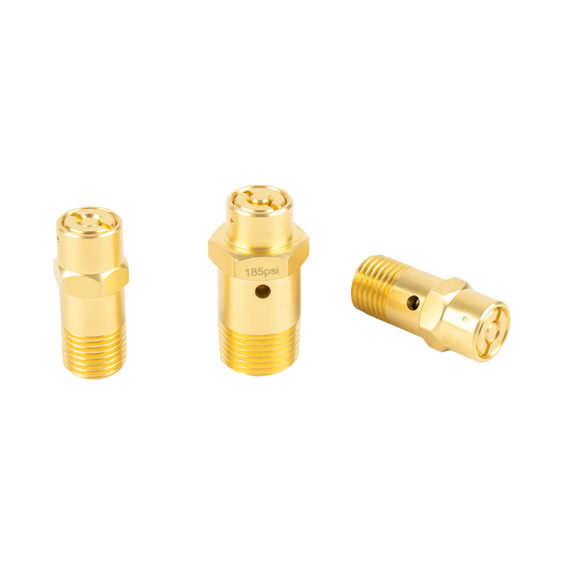 Safety Valve Assembly for Controlled Overpressure ReleaseThis safety valve assembly is designed to vent excess pressure automatically, helping protect pressure-sensitive automotive components and maintain controlled pressure release in high-pressure systems.View Product →
Common Failures and What They Signal
Most engine problems are the four-stroke cycle degrading in a recognizable pattern. Reading the symptom against the cycle narrows the diagnosis quickly. The table below maps frequent symptoms to their likely mechanical causes and the damage they cause if ignored.
| Symptom | Likely Cause | Untreated Result |
|---|---|---|
| Misfire at idle or under load | Weak spark, faulty injector, low compression | Catalyst damage, power loss, rough idle |
| Knocking under acceleration | Low-octane fuel, carbon buildup, timing too advanced | Piston crown erosion, bearing damage |
| Blue or gray exhaust smoke | Worn piston rings, leaking valve stem seals | Fouled spark plugs, rising oil consumption |
| Engine overheating | Water pump failure, stuck thermostat, blocked radiator | Warped cylinder head, failed head gasket |
| Hard starting when hot | Vapor lock, leaky injector, low cranking compression | Starter strain, intermittent no-start |
Note how many causes trace back to sealing and timing. A compression leak past a valve seat produces the same misfire as a failing ignition coil, which is why changing parts without diagnosis wastes time. The four-stroke framework tells you where to look first: if compression is suspect, check the valve train before replacing electronics.
Electrified Valve Control: Solenoids in Engine and Air Systems
Engines are no longer purely mechanical when it comes to valve timing. Variable valve timing systems shift camshaft phase using hydraulic pressure commanded by solenoid control valves, optimizing valve overlap across the entire rev range. Modern trucks use solenoid pilot valves in a similar way, controlling pneumatic braking, air suspension, and auxiliary air circuits with electrical signals instead of long mechanical linkages.
Solenoid failure modes are consistent across these applications: an open or shorted coil, a plunger stuck by debris, or a seal that no longer holds pressure. Diagnosis follows a repeatable sequence — check coil resistance, apply and release power while watching response time, and inspect the seat and plunger surfaces. The manufacturing demands are equally consistent: dimensional stability, corrosion-resistant materials, and seals that keep their geometry through temperature cycles.
 Solenoid Valve Assembly A for Automotive Fluid and Pressure ControlBuilt for electromagnetic flow control in automotive systems, this solenoid valve assembly is relevant where reliable actuation, leakage resistance, and precise fluid or pressure regulation are required.View Product →
What Keeps an Engine Reliable Over Time
Fleet experience confirms that three conditions decide an engine's life span: clean oil, proper cooling, and valve timing that stays within specification. The maintenance habits that protect those conditions are simple, but skipping any one accelerates wear across the whole cycle.
- Oil change intervals. Severe service — heavy loads, prolonged idling, dusty sites — degrades oil faster than highway cruising, so shorten intervals accordingly and use oil that meets the OEM specification.
- Coolant condition. Corrosion inhibitors expire even when the temperature gauge looks normal. Scheduled flushes prevent electrolysis damage inside aluminum cylinder heads.
- Valve adjustment. Mechanical valve trains require periodic lash checks. A valve left tight opens early and closes late, effectively shifting the timing map by the distance between the adjuster and the valve stem.
- Air filter replacement. A clogged filter restricts breathability, raising fuel consumption and exhaust temperature. Replace it by restriction reading or interval, whichever comes first.
The same habit of choosing verified, precision-made parts applies to pneumatic hardware. Whether the component is an engine valve seat or an air tank relief valve, tolerances and finishes determine service life. For reference, the ZEAST Autoparts product catalog demonstrates how a single manufacturer groups pneumatic brake valves, valve cylinder assemblies, machining parts, and rubber components — a useful starting point when sourcing matched parts for a fleet.