

 English
 русский
 中文简体
中文简体normally open and normally closed: Practical Applications, Selection, Performance
2026-09-28
Content
- 1 "Normal" Means the State With No Command Applied
- 2 Normally Open: The Path That Stays Shut Until Called
- 3 Normally Closed: Conducting or Flowing by Default
- 4 NO vs NC at a Glance
- 5 Why Fail-Safe Design Usually Picks NC
- 6 Reading Real Air Brake Hardware: Where NO and NC Show Up
- 7 A Field Sequence for Specifying NO or NC
- 8 The Resting State Is the Failure State
A maintenance supervisor once replaced a reservoir drain valve that looked identical to the original. It threaded in cleanly and held air at rest. But the original kept condensate trapped until a control command purged it; the replacement passed air in its resting position. Within minutes, the chassis pressure bled down. The cause was not threads or materials. It was the difference between normally open and normally closed behavior.
In electrical contacts and pneumatic valves, these two terms describe the position a device holds when nobody is commanding it. A spring holds a contact gap open or closed; a valve spring parks a spool or poppet at a fixed arrangement of ports. The solenoid, button, or pilot signal only moves the device away from that base position temporarily.
That is not a minor specification detail. In an air brake system, it decides the failure direction when power or air disappears. That makes the choice a safety property, not a preference.
"Normal" Means the State With No Command Applied
In component terminology, "normal" has nothing to do with usual, expected, or ideal machine operation. It means the physical resting state when all actuating forces are absent. For a contact, that state comes from mechanical construction: a spring either holds the movable contact away from the fixed contact (NO) or pushes it against that contact (NC). For a pneumatic valve, it is the position the spool or poppet takes when the solenoid carries no current and the pilot port sees no pressure.
You can observe it directly. Remove the coil, vent the pilot line, and watch where the spool lands. That position, visible and repeatable, is "normal." Everything in the control system is designed around that starting point, which is why reading a valve's resting state before installation is a habit worth keeping.
Normally Open: The Path That Stays Shut Until Called
A normally open device does nothing in its resting position. Contacts are separated, so no current flows. Valve ports are blocked, so no air moves. Only after an actuating command, such as coil current, a button press, or pilot pressure, does it change state.
- At rest: blocked or non-conducting.
- When actuated: open and passing flow or current.
- When supply is lost: returns to blocked.
NO suits occasional, on-demand functions. A purge port, a fill line, or a signal circuit that must stay dead during normal running is a natural fit: nothing flows until the control system calls for it, which saves air and energy.
The trade-off is silent downtime. If the solenoid coil fails or control air is lost, the device simply stays closed. Nothing dramatic happens; the function just quietly stops. A missed purge contaminates a reservoir gradually, without an alarm, which makes NO faults harder to trace.
Normally Closed: Conducting or Flowing by Default
A normally closed component is the mirror image. Its resting position completes an electrical path or keeps an air path passing. It changes state only when actuated, so it conducts or flows by default and waits for a command to interrupt it.
- At rest: conducting or flowing.
- When actuated: interrupted or blocked.
- When supply is lost: returns to conducting or flowing.
NC is the default choice for safety-monitoring chains. Emergency stop buttons, guard-door switches, and safety relays are wired as a series loop of NC contacts: a broken wire, a pressed e-stop, or a de-energized relay opens the loop, and the monitoring circuit drops the load. The healthy state is visible at every moment because current is flowing.
The same intent appears in pneumatics. A spring-loaded seat that seals the flow path at rest is NC. A safety valve assembly holds its seat closed across the normal pressure range and only relieves above a set threshold. All day, it does nothing visible, by staying closed.
NO vs NC at a Glance
Two questions matter more than the label: what does the component do at rest, and what does it do when the command disappears? The comparison below covers both.
| Property | Normally Open (NO) | Normally Closed (NC) |
|---|---|---|
| Contact or valve position at rest | Separated or blocked | Touched or passing flow |
| Effect of actuating | Closes the gap / opens the flow path | Opens the gap / interrupts the flow path |
| Effect of losing supply | Returns to blocked / non-conducting | Returns to flowing / conducting |
| Typical role | On-demand functions, intermittent signals | Continuous readiness, safety chains |
| Main failure risk | Function silently stops | Function may resume when unpowered |
In both columns, the important moments are the quiet ones: what happens at rest, and what happens after the command is removed.
Why Fail-Safe Design Usually Picks NC
The design question is simple: when the system loses the energy it needs to act, what should it fall back to? In most safety circuits, the answer is "stop," which is why the monitoring chain uses NC contacts in series.
- Build the chain with NC contacts in series. Every e-stop and guard-door switch sits in a continuously conducting loop.
- Treat any open in the loop as the trip event. A broken wire or a de-energized relay interrupts the chain, and the control unit removes power from the hazardous motion.
- Let the spring decide the pneumatic failure state. If the safe behavior is pressure blocked or a brake applied, the spool should rest in the NC position.
NO logic has an inherent gap: a fault stays invisible until someone calls for the function. NC logic keeps the healthy state visible and testable. That is why specifiers in brake and valve systems check the de-energized position first. The resting state and the fail-safe state should be the same position.
Reading Real Air Brake Hardware: Where NO and NC Show Up
Air brake components do not carry terminals labeled NO and NC. You read the mechanical intent, meaning the spring position when no command exists.
Safety valve assemblies are NC in design. A spring holds the seat closed over the normal working range, and the valve only opens above its calibrated relief threshold. During normal service, it does nothing, by staying closed.
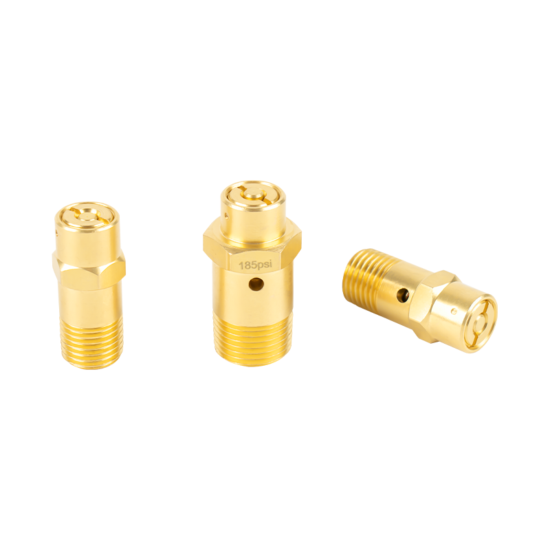 Safety Valve Assembly for Overpressure ProtectionSpring-loaded and normally closed, this safety valve opens only above its calibrated relief threshold, protecting automotive systems from overpressure while remaining inactive during normal service.View Product →
Blowdown and drain valves also rest NC. The reservoir port remains sealed under spring force, and a control signal opens the valve deliberately to discharge condensate when pressure conditions are favorable. Fit an NO version in that position, and the reservoir bleeds air until the compressor cycles continuously.
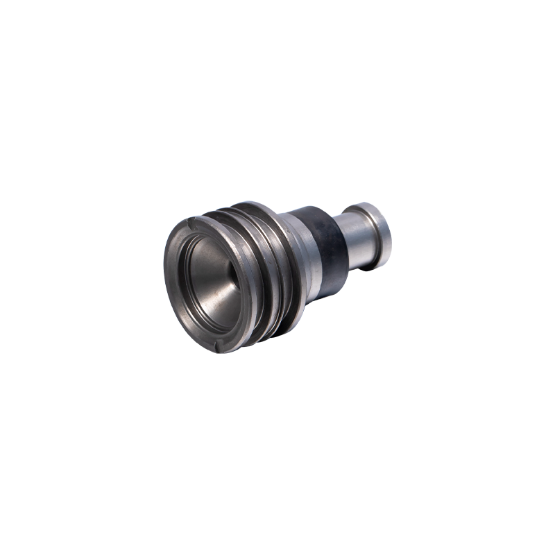 Blowdown Valve for Condensate DischargeDesigned for safe pressure release, this blowdown valve stays normally closed and opens on command to discharge condensate, helping maintain system pressure and prevent overpressure.View Product →
Relay valves are a warning against forcing everything into two states. They are pilot-operated proportioning valves: a small control pressure opens the supply passage and modulates brake-chamber pressure. The discipline is the same: check where the spool parks when the pilot is vented, then confirm the circuit behaves as drawn.
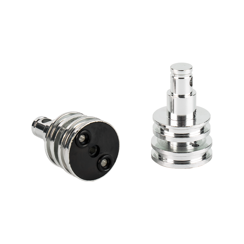 Relay Valve A for Pneumatic Brake SystemsA pilot-operated proportioning valve that uses a small control pressure to modulate brake-chamber pressure, this relay valve improves responsiveness and reduces pressure fluctuations.View Product →
A manufacturer such as ZEAST Autoparts supplies these valve families for commercial air brake systems, and the field rule for any of them is identical: bench-test the resting position before installation, and verify the failure direction afterward. For a wider look at valve types and operating logic, the pneumatic brake valve guide covers the system-level picture.
A Field Sequence for Specifying NO or NC
Instead of memorizing which state an industry "usually" uses, run through this sequence every time you order or replace a valve.
- Name the failure you are protecting against. What must happen when the solenoid is off or the pilot line is vented? Seal the port, or keep it open?
- Read the spring, not the label. Whatever position the spool rests in is the normal state, regardless of what the data sheet calls it.
- Verify ports at rest with shop air. Apply no command and confirm which ports connect; mark them on the body before installation.
- Test the failure direction in the installed circuit. Remove control energy and confirm the machine moves to the expected state every time.
- Stop if a replacement behaves differently at rest. The original circuit depends on a specific default state; confirm it before proceeding.
Most field troubleshooting time is spent on exactly this confusion: technicians assume they know the difference, then discover that "normal" was defined differently by the machine designer.
The Resting State Is the Failure State
When a pneumatic or electrical component fails, it does not fall toward whatever seems safer. It falls toward whatever the spring holds when no energy remains. That rule makes normally open and normally closed far more than a terminology quiz.
Choose the resting state that matches the failure state you can live with. When control energy disappears, the system will go exactly there, every time.