English
 русский
 中文简体
中文简体How Often Should Safety Valves Be Inspected? A Complete Guide
2026-04-06
Content
- 1 How Often Should Safety Valves Be Inspected?
- 2 Industry Standards That Govern Safety Valve Inspection Intervals
- 3 Recommended Inspection Intervals by Application Type
- 4 Factors That Determine How Often Safety Valves Need Inspection
- 5 Types of Safety Valve Inspections and What Each Involves
- 6 Risk-Based Inspection (RBI) as an Alternative to Fixed Intervals
- 7 Common Failure Modes Found During Safety Valve Inspection
- 8 Documentation and Record-Keeping Requirements
- 9 What Happens When Safety Valve Inspections Are Missed
- 10 Practical Steps for Building a Safety Valve Inspection Program
- 11 Differences Between Safety Valve Types and Their Inspection Implications
How Often Should Safety Valves Be Inspected?
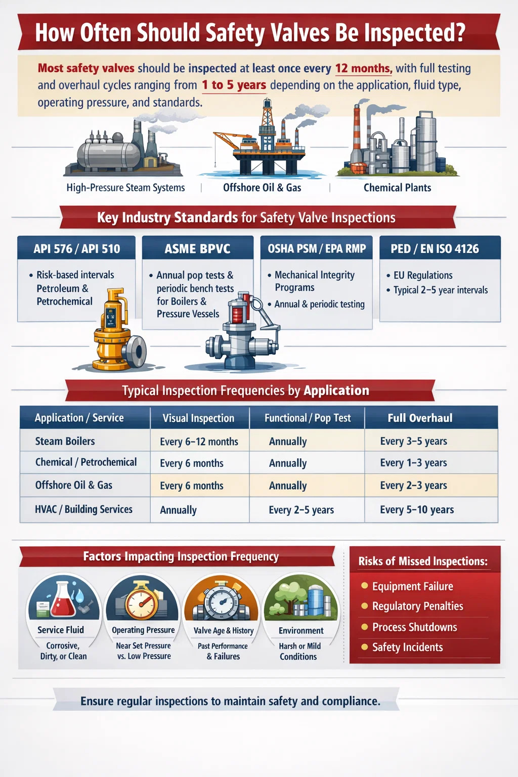
The direct answer: most safety valves should be inspected at least once every 12 months, with full testing and overhaul cycles ranging from 1 to 5 years depending on the application, fluid type, operating pressure, and applicable regulatory standards. However, this is not a one-size-fits-all rule. High-pressure steam systems, chemical processing plants, and offshore oil installations each carry their own inspection intervals, and failure to follow the correct schedule can result in catastrophic equipment failure, regulatory penalties, or loss of life.
Safety valves — also referred to as pressure relief valves (PRVs), pressure safety valves (PSVs), or relief valves depending on the context — are among the most critical components in any pressurized system. Their sole purpose is to open at a predetermined set pressure and release excess pressure before it can damage equipment or endanger personnel. When they fail to open, the consequences range from damaged pipework to catastrophic vessel explosions. When they fail to close properly after opening, they create costly process losses and introduce contamination risks.
Getting the inspection frequency right is therefore not a minor administrative task. It is a core element of plant safety management, process integrity, and legal compliance.
Industry Standards That Govern Safety Valve Inspection Intervals
Several major international standards and codes define the framework for how frequently safety valves must be tested and inspected. Understanding which standard applies to your operation is the starting point for building any inspection program.
API 510 and API 576
The American Petroleum Institute's API 576 (Inspection of Pressure-Relieving Devices) is the most widely referenced standard globally for pressure relief valve inspection in the petroleum and petrochemical industries. API 576 does not mandate a fixed interval but instead provides a risk-based framework. It states that inspection intervals should be based on the history of the valve, the service conditions, and the consequences of failure. Typical intervals referenced in industry practice under API 576 range from 5 years for clean, non-corrosive services to as frequently as annually or less for fouling, corrosive, or dirty services.
API 510 (Pressure Vessel Inspection Code) complements this by requiring that pressure-relieving devices be inspected and tested on a schedule determined by a qualified inspector or process safety engineer, taking into account the service environment and any history of malfunction.
ASME Boiler and Pressure Vessel Code (BPVC)
The ASME BPVC Section I (Power Boilers) and Section VIII (Pressure Vessels) require that safety valves on boilers and pressure vessels be tested regularly. For power boilers, many jurisdictions require a physical pop test at least once per year, often during scheduled outages. ASME standards also require that any valve that has been in service for a certain period be removed for bench testing, with intervals typically not exceeding 5 years in most jurisdictions.
OSHA PSM and EPA RMP Requirements
In the United States, facilities covered under OSHA's Process Safety Management (PSM) standard (29 CFR 1910.119) and the EPA's Risk Management Program (RMP) must maintain a Mechanical Integrity program that includes pressure-relieving devices. These regulations require documented inspection and testing procedures, written records of all inspections, and corrective action when deficiencies are found. While the regulations do not specify a universal interval, they require the employer to establish intervals based on manufacturers' recommendations and good engineering practice — which in practice typically means annual visual inspections and periodic functional tests.
PED and EN ISO 4126 (European Union)
In Europe, the Pressure Equipment Directive (PED 2014/68/EU) and the associated standard EN ISO 4126 govern the design and safety requirements for pressure-relieving devices. National regulations in EU member states then specify inspection intervals. In Germany, for instance, the BetrSichV (Industrial Safety Regulation) typically requires safety valve testing every 2 to 5 years depending on the pressure class and fluid category, with annual visual inspections in most industrial settings.
Recommended Inspection Intervals by Application Type
Because no single interval applies universally, the table below summarizes the recommended or commonly practiced inspection frequencies across major application categories.
| Application / Service Type | Visual Inspection | Functional / Pop Test | Full Overhaul / Bench Test |
|---|---|---|---|
| Steam boilers (industrial) | Every 6–12 months | Annually | Every 3–5 years |
| Oil & gas upstream / midstream | Annually | Every 2–3 years | Every 5 years (clean service) |
| Chemical / petrochemical (corrosive) | Every 6 months | Annually | Every 1–3 years |
| Pharmaceutical / food processing | Every 6–12 months | Annually | Every 2–3 years |
| HVAC / building services | Annually | Every 2–5 years | Every 5–10 years |
| Offshore oil & gas | Every 6 months | Annually | Every 2–3 years |
| Power generation (utility boilers) | Every 6 months | Annually (during outage) | Every 3–5 years |
Factors That Determine How Often Safety Valves Need Inspection
Inspection frequency is never determined in isolation. A range of operational and environmental factors must be evaluated when setting or adjusting the inspection schedule for any pressure relief valve.
Service Fluid Characteristics
The nature of the fluid flowing through the system has perhaps the greatest influence on how quickly a safety valve degrades. Fluids can be classified broadly as clean, fouling, or corrosive, and each category demands different inspection intervals.
- Clean steam or inert gas: These are the most forgiving services. Valves may remain reliable for up to 5 years between full overhauls if operating conditions are stable.
- Corrosive acids or alkalis: Chemical attack on the disc, seat, and spring can degrade set pressure accuracy significantly within 12 months. Annual functional testing is the minimum acceptable frequency.
- Dirty or polymerizing services: Fluids that carry solids or that polymerize over time can cause the valve disc to stick to the seat — known as "valve simmer" or "seat locking" — rendering the valve inoperable when needed. These applications require the most frequent inspection intervals, sometimes as short as every 3 to 6 months.
- Viscous or high-temperature fluids: These accelerate wear on internal components and can cause thermal fatigue in the spring assembly.
Operating Pressure Relative to Set Pressure
Safety valves that operate close to their set pressure experience a phenomenon known as "simmer," where the disc lifts slightly before the full relieving pressure is reached. This repeated partial lifting causes seat wear and can lead to leakage, reducing the valve's ability to seal effectively. Valves operating at more than 90% of their set pressure should be inspected more frequently than those operating at 70% or below. The general recommendation is to maintain an operating pressure no higher than 90% of the set pressure for spring-loaded valves and no higher than 80% for pilot-operated relief valves in sensitive applications.
Valve Age and Historical Performance
A valve with a clean inspection history and consistent set pressure readings over multiple test cycles may justify a longer interval between overhauls. Conversely, a valve that has previously failed a pop test, leaked at the seat, or required set pressure adjustment should be placed on a shorter inspection cycle regardless of the general service category. This historical approach is the foundation of risk-based inspection (RBI) methodologies widely used in the oil and gas sector.
Number of Actuations
Each time a safety valve opens and closes, the seating surfaces experience mechanical impact. High-cycling valves — those that open frequently due to process instability or oversizing — wear out significantly faster than valves that rarely actuate. A valve that has opened more than 10 times in a service period should be visually inspected and functionally tested before the next scheduled interval.
Ambient and Environmental Conditions
Outdoor installations in humid, marine, or highly polluted environments corrode faster than indoor installations. Valves exposed to direct rainfall, salt spray, or high-humidity atmospheres require more frequent external inspections to check for cap vent blockages, body corrosion, and spring housing integrity.
Types of Safety Valve Inspections and What Each Involves
Not every inspection is the same in scope. There are four distinct levels of inspection activity, each serving a different purpose and requiring a different level of skill and resources.
Level 1: Visual External Inspection
This is the most basic and most frequently performed check. It does not require the valve to be removed from service. A trained operator or inspector visually examines the valve for:
- Signs of leakage past the seat (process fluid residue, staining, crystalline deposits)
- Corrosion, pitting, or mechanical damage on the valve body and bonnet
- Blocked or damaged vent caps and drain holes
- Loose or missing tamper seals and locking pins
- Correct installation orientation and discharge piping condition
- Legible nameplate data matching the engineering records
Visual inspections should be performed at least annually for most industrial applications and every 3 to 6 months in aggressive service environments.
Level 2: In-Situ Functional Testing
In-situ testing — also called online testing or field testing — verifies that the valve will open at or near its designated set pressure without removing it from the process line. This is typically performed using one of two methods:
- Manual lift test: A lift lever is used to partially open the valve to verify free movement of the disc. This is a qualitative check only and does not verify set pressure accuracy.
- Controlled pressure test: Using portable test equipment (such as HYTORK or Furmanite test tools), controlled pressure is applied to the valve inlet while it remains connected to the system. The actual opening pressure is measured and compared to the stamped set pressure.
In-situ testing is valuable because it avoids the cost and process disruption of valve removal while still generating quantitative data. However, it has limitations: it cannot assess internal corrosion or seat condition in detail.
Level 3: Bench Testing (Pop Test)
Bench testing requires removing the valve from service and transporting it to a workshop or valve testing facility. The valve is mounted on a test stand and pressurized until it opens. The actual opening pressure, seat tightness, and reseating pressure are all measured and documented. ASME standards require that the opening pressure be within ±3% of the stamped set pressure for most applications (±2% for steam service above 70 psig).
Bench testing is the most accurate method for verifying valve performance and is required by most regulatory authorities for pressure vessels and boilers at regular intervals. It also allows the inspector to examine the internal components directly.
Level 4: Full Disassembly, Inspection, and Overhaul
A full overhaul involves complete disassembly of the safety valve, inspection of all internal components, replacement of wear parts (disc, nozzle seat, spring, seals, and guide), reassembly, and bench testing before reinstallation. This is the most comprehensive form of inspection and is typically required every 3 to 5 years, or whenever a valve has failed a functional test, been involved in a process upset, or been exposed to an abnormal event such as a fire case or severe overpressure.
After a full overhaul, the valve must be recertified, resealed with tamper-evident wire seals, and its inspection records updated with the new set pressure test data, parts replaced, and the identity of the technician performing the work.
Risk-Based Inspection (RBI) as an Alternative to Fixed Intervals
The traditional approach of applying a fixed inspection interval — say, every 2 years for all safety valves in a plant — is increasingly being replaced by Risk-Based Inspection (RBI). RBI is a methodology that combines the probability of failure with the consequences of failure to determine the most appropriate inspection strategy for each individual valve.
Under RBI, a safety valve protecting a high-pressure steam drum in a power plant might be inspected annually, while a relief valve on a low-pressure nitrogen purge system in the same facility might only require inspection every 5 years. This targeted approach reduces unnecessary maintenance costs while focusing resources on the highest-risk equipment.
API 581 (Risk-Based Inspection Technology) provides a detailed methodology for applying RBI to pressure-relieving devices. A key output of the RBI process is a demand rate analysis — an estimate of how often a safety valve is likely to be called upon to open in a given period. Valves with high demand rates need more frequent inspection to confirm they remain functional. Valves with very low demand rates may qualify for longer intervals, but only if their consequence of failure is also low.
For facilities with large numbers of safety valves, RBI can result in 30% to 50% reductions in total inspection workload compared to fixed-interval programs, without compromising safety — provided the risk analysis is conducted rigorously and kept up to date as process conditions change.
Common Failure Modes Found During Safety Valve Inspection
Understanding what inspectors actually find when they examine safety valves reinforces why regular inspection matters. The following failure modes are the most frequently documented across industrial inspection programs.
Seat Leakage
Seat leakage — where the valve allows a continuous small flow of fluid to pass even when fully closed — is the most common defect found during bench testing. It results from seat surface damage caused by simmer, corrosion, or solid particle impingement. A leaking safety valve not only represents a process loss but can also cause the disc to erode further over time, leading to complete loss of sealing ability. Industry studies indicate that between 25% and 40% of safety valves removed from service have measurable seat leakage at the time of inspection.
Set Pressure Drift
Springs can lose tension over time due to thermal cycling, corrosion, or material fatigue. This causes the actual opening pressure to drift below or above the stamped set pressure. A valve with a set pressure of 100 psi that has drifted to open at 80 psi provides insufficient protection against overpressure. Conversely, a valve that has drifted upward and now opens at 115 psi exposes the system to potentially damaging overpressure before the valve relieves. Set pressure drift of more than 5% from the stamped value typically requires spring replacement and recertification.
Blocked Discharge Piping or Vent
Discharge piping that has become blocked — due to bird nesting, ice formation, debris accumulation, or incorrect valve installation — creates backpressure that can prevent the valve from opening at its set pressure. This is a particularly dangerous failure mode because the valve may appear fully functional during visual inspection while actually being incapable of relieving. Discharge piping must be inspected for blockages, excessive back pressure potential, and correct drainage routing at every scheduled inspection.
Disc or Nozzle Corrosion
Internal corrosion of the disc and nozzle seat surfaces is a significant issue in wet steam, acid service, or chloride-containing environments. Pitting of these precision-machined surfaces destroys the metal-to-metal seal that the valve depends on for tight shutoff after relieving. Once the seating surfaces are pitted, grinding and lapping can restore them to a limited extent, but severely corroded components must be replaced entirely.
Spring Corrosion or Fatigue
The compression spring inside a safety valve is a critical load-bearing component. Corrosion pitting on the spring wire reduces its effective cross-section, which can cause unexpected fracture under operating stress. Fractured springs have been documented as the root cause of catastrophic safety valve failures in several industrial incidents. Springs showing any visible corrosion, deformation, or surface cracking must be replaced immediately.
Documentation and Record-Keeping Requirements
Every safety valve inspection must be thoroughly documented. Regulatory standards — including OSHA PSM, API 510, and most European national regulations — require written records that can be audited to demonstrate compliance. The inspection record for each valve should include:
- Valve tag number, serial number, and location in the process
- Stamped set pressure and the measured opening pressure during testing
- Date of inspection and the identity of the qualified inspector or technician
- Description of any defects found and the corrective actions taken
- Parts replaced during overhaul
- Post-repair bench test results
- Next scheduled inspection date
- Seal number applied after testing (to detect unauthorized adjustment)
These records must be retained for the life of the equipment in most jurisdictions, and at minimum for a period extending well beyond the next inspection interval. Many facilities use computerized maintenance management systems (CMMS) such as SAP PM or IBM Maximo to manage safety valve inspection records alongside other asset management data.
It is worth noting that the absence of proper inspection records is itself a regulatory violation under OSHA PSM, regardless of whether the valves are actually in good condition. During a PSM audit or process incident investigation, inspectors will request these records as primary evidence of mechanical integrity compliance.
What Happens When Safety Valve Inspections Are Missed
The consequences of failing to inspect safety valves on schedule are not theoretical. Several major industrial incidents in recent decades have been directly or partially attributed to pressure relief valve failures caused by inadequate inspection.
In the 2005 BP Texas City refinery explosion, which killed 15 workers and injured 180 others, investigation findings included inadequate maintenance and inspection of pressure relief systems as a contributing factor. The subsequent OSHA investigation resulted in fines exceeding $21 million, with mechanical integrity program failures — including inadequate pressure relief device management — cited prominently.
More routine consequences of missed safety valve inspections include:
- Regulatory penalties: OSHA PSM citations for mechanical integrity failures typically carry penalties of $15,000 to $156,259 per violation, with willful violations reaching higher levels.
- Insurance implications: Many industrial property and liability insurers require evidence of valve inspection compliance as a condition of coverage. A missed inspection cycle can void coverage for any incident involving pressure system failure.
- Unplanned shutdowns: A safety valve that fails open or stuck-open during an operational event can trigger a forced shutdown that, in a continuous process plant, can cost hundreds of thousands of dollars per day in lost production.
- Cascading equipment damage: A safety valve that fails to open during a genuine overpressure event exposes the protected vessel, heat exchanger, or piping to pressures exceeding their design limits, potentially causing rupture and downstream damage to other equipment.
Practical Steps for Building a Safety Valve Inspection Program
For facilities that are establishing or improving a safety valve management program, the following sequence provides a structured approach.
- Create a complete valve register: Compile a list of every safety valve in the facility, including tag number, location, service fluid, set pressure, inlet size, body material, and installation date. This register is the foundation of the entire program.
- Classify valves by service severity: Assign each valve to a service category — clean, fouling, or corrosive — and identify those with high demand rates or high consequence of failure. These classifications will drive the inspection frequency decisions.
- Define inspection intervals: Using the applicable regulatory standard (API 576, ASME, local regulations), set a specific inspection interval for each valve or valve group. Document the rationale for each assigned interval, particularly if deviating from the standard default.
- Schedule inspections against planned maintenance windows: Where possible, align safety valve testing with planned shutdowns or turnarounds to minimize production impact. For online testing programs, schedule in-situ tests during periods of stable operation.
- Qualify your testing resources: Ensure that inspectors and technicians performing safety valve work are qualified to the applicable standard. ASME Section VIII, for example, requires that valve testing be performed by personnel working under a National Board (NB) "VR" stamp for repair and testing work.
- Maintain and review inspection records: After each inspection, update the valve register with test results, findings, and the next scheduled date. Review the overall program annually to adjust intervals based on accumulated inspection history.
- Investigate every failure: Any valve that fails a functional test — whether it opens early, opens late, or fails to reseat — should trigger a formal root cause investigation before the valve is returned to service. Understanding why a valve failed is essential for preventing recurrence and for justifying any interval adjustment.
Differences Between Safety Valve Types and Their Inspection Implications
Not all pressure relief devices are the same, and the type of device installed affects how it should be inspected and how often.
Spring-Loaded Safety Valves
The most common type in industrial applications. The opening pressure is determined by the spring force acting on the disc. Spring-loaded valves are subject to spring fatigue, seat wear, and corrosion. They require both external visual inspection and periodic pop testing to verify set pressure. Full overhaul intervals typically range from 1 to 5 years depending on service.
Pilot-Operated Relief Valves (PORVs)
PORVs use a small pilot valve to sense system pressure and actuate the main valve. They are capable of tighter shutoff and can handle larger flow rates more efficiently than spring-loaded valves. However, they have a more complex internal mechanism — including the pilot valve, tubing, and sensing connections — all of which are potential failure points. PORVs generally require more detailed inspection procedures than spring-loaded valves, and the pilot assembly must be tested separately from the main valve. Annual inspection of the pilot system is standard practice in most process industries.
Rupture Discs
Rupture discs are non-reclosing pressure relief devices that burst at a predetermined pressure to provide instantaneous relief. Unlike safety valves, they do not require pop testing — their "inspection" consists primarily of verifying that the disc has not been visually damaged, that the burst pressure marking matches the design requirements, and that the disc has not been in service beyond its recommended service life. Most rupture disc manufacturers recommend replacement every 3 to 5 years regardless of condition, as fatigue and corrosion can cause premature burst or prevent burst at the rated pressure.
Combination Devices (Rupture Disc + Safety Valve)
Many processes use a rupture disc installed upstream of a safety valve to protect the valve from corrosive or polymerizing fluids. This combination requires inspection of both devices — the rupture disc for integrity and the safety valve for set pressure accuracy. A critical additional requirement is monitoring the pressure in the space between the rupture disc and the safety valve. If the disc develops a small leak and the inter-device space pressurizes, the safety valve will experience backpressure that reduces its effective relieving capacity. A pressure gauge or burst indicator on this space is mandatory per ASME code and must be checked at every inspection.