English
 русский
 中文简体
中文简体How to Size a Safety Valve: A Complete Technical Guide
2026-04-13
Content
- 1 The Short Answer: How to Size a Safety Valve
- 2 Why Proper Safety Valve Sizing Matters More Than Most Engineers Realize
- 3 Key Terms You Must Understand Before Sizing
- 4 Step-by-Step: How to Size a Safety Valve for Gas or Vapor Service
- 5 Sizing a Safety Valve for Steam Service
- 6 Sizing a Safety Valve for Liquid Service
- 7 Standard Orifice Sizes: API 526 Reference Table
- 8 How Back Pressure Affects Safety Valve Selection and Sizing
- 9 Two-Phase and Mixed-Phase Relief: Special Considerations
- 10 Inlet Pressure Drop: The 3% Rule That Gets Ignored
- 11 Fire Case Sizing: When Thermal Relief Dominates
- 12 Common Sizing Mistakes and How to Avoid Them
- 13 Safety Valve Sizing Software and Tools
- 14 Regulatory and Code Requirements Summary
- 15 Practical Checklist for Safety Valve Sizing
The Short Answer: How to Size a Safety Valve
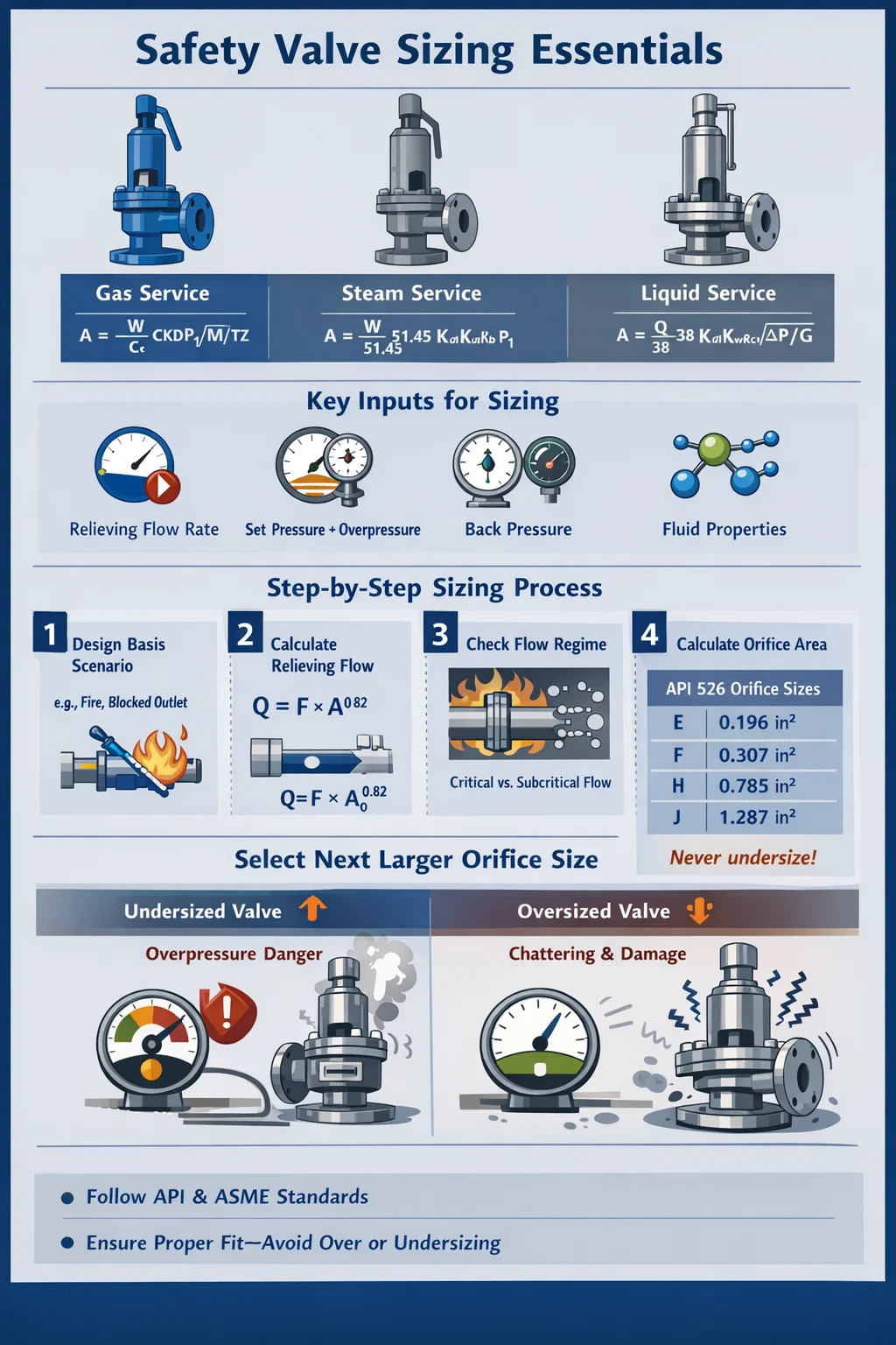
To size a safety valve, you need to calculate the required relieving capacity in mass or volumetric flow, then select a valve orifice area large enough to pass that flow at the valve's set pressure plus allowable overpressure. The governing formula depends on the fluid phase—gas, steam, or liquid—and standards such as API 520 Part I, API 526, and ASME Section VIII Div. 1 define the exact calculation method.
In practice, sizing a pressure relief valve or safety relief valve involves four core inputs:
- Required relieving flow rate (kg/h or lb/h)
- Set pressure and allowable overpressure (typically 10% for single valve installations per ASME)
- Back pressure at the valve outlet
- Fluid physical properties at relieving conditions
Once you calculate the required orifice area, you select the next standard orifice size larger from API 526 tables—never smaller. An undersized safety valve fails to protect the vessel; an oversized one chatters, erodes, and leaks.
Why Proper Safety Valve Sizing Matters More Than Most Engineers Realize
A safety valve is the last line of defense between normal operation and a catastrophic overpressure event. Undersizing means the valve cannot flow fast enough to prevent the vessel from exceeding its maximum allowable working pressure (MAWP). Oversizing creates a different but equally serious problem: the valve opens, relieves a small amount of fluid, closes, and then opens again in rapid succession—a destructive condition called chatter.
Chatter causes seat damage within minutes. A chattering safety relief valve that should last 10 years may be destroyed in a single event lasting less than an hour. Maintenance costs for valve seats, discs, and nozzles can run from $2,000 to $20,000 per valve, not counting lost production.
Beyond economics, regulatory compliance is mandatory. In most jurisdictions, pressure vessels must be protected by relief devices sized and stamped in accordance with recognized codes. In the United States, ASME Boiler and Pressure Vessel Code Section VIII is the primary standard. In Europe, the Pressure Equipment Directive (PED) and EN ISO 4126 govern the design. Failure to comply creates legal liability and can void equipment insurance.
Key Terms You Must Understand Before Sizing
Safety valve sizing has its own vocabulary. Misunderstanding even one term can lead to a calculation error that propagates through the entire sizing exercise.
Set Pressure
The inlet pressure at which the safety valve is set to open. For a vessel with a MAWP of 100 barg, the set pressure must not exceed 100 barg. Set pressure is stamped on the valve nameplate and tested during bench setting.
Overpressure
The pressure increase above set pressure that occurs while the valve is open and flowing. ASME allows 10% overpressure for a single safety valve and 16% for fire cases. The relieving pressure equals set pressure plus overpressure.
Back Pressure
Pressure at the valve outlet, caused by the discharge piping system. Back pressure reduces the differential pressure across the valve and therefore reduces capacity. There are two types:
- Superimposed back pressure — exists before the valve opens, due to a pressurized header or closed outlet.
- Built-up back pressure — develops only when the valve is flowing, due to friction losses in the discharge pipe.
Conventional safety valves are sensitive to back pressure. If built-up back pressure exceeds 10% of set pressure, a balanced bellows or pilot-operated pressure relief valve should be considered.
Coefficient of Discharge (Kd)
A dimensionless factor that accounts for flow losses through the valve body. API 520 uses a rated coefficient of discharge, Kd, which is typically around 0.975 for gas/vapor service and 0.65 for liquid service. Manufacturers publish certified Kd values from ASME flow tests.
Required Orifice Area (A)
The minimum flow area calculated from your relieving duty. You then match this to the next larger standard orifice designation from API 526 (D, E, F, G, H, J, K, L, M, N, P, Q, R, T).
Step-by-Step: How to Size a Safety Valve for Gas or Vapor Service
Gas and vapor sizing uses compressible flow equations. The API 520 Part I methodology is the industry standard for this. Follow these steps in order.
Step 1: Identify the Design Basis Scenario
You must first determine what causes the overpressure. Common scenarios include blocked outlet, cooling water failure, fire exposure, heat exchanger tube rupture, and runaway reaction. Each scenario produces a different required relieving flow. Size for the worst credible single case unless the installation philosophy requires simultaneous cases.
Step 2: Calculate Required Relieving Flow
This comes from a process simulation or heat and material balance. For a blocked outlet on a compressor, the required flow equals the full compressor throughput. For fire cases, API 521 provides the heat input formula:
Q = 43,200 × F × A0.82 (for wetted surface, in BTU/h, imperial units)
where F is an environment factor (1.0 for bare vessels, 0.3 for adequately insulated vessels) and A is the wetted surface area in square feet.
Step 3: Check for Critical or Subcritical Flow
Flow through a safety valve nozzle becomes critical (choked) when the ratio of back pressure to relieving pressure falls below the critical pressure ratio Cf. For an ideal gas, Cf depends on the ratio of specific heats (k or γ):
Cf = (2/(k+1))k/(k-1)
For most hydrocarbons and air, k ≈ 1.3–1.4, giving Cf ≈ 0.545–0.528. If back pressure / relieving pressure is below Cf, you have critical flow and use the simpler critical flow equation. Otherwise, use the subcritical correction.
Step 4: Apply the API 520 Gas Sizing Formula
For critical gas flow (API 520 Part I, Equation 3):
A = W / (C × Kd × P1 × Kb × √(M / (T × Z)))
- A = required orifice area (in²)
- W = required relieving capacity (lb/h)
- C = gas constant derived from k (dimensionless, tabulated in API 520 Appendix B)
- Kd = effective coefficient of discharge (use 0.975 for preliminary sizing)
- P1 = relieving pressure in psia (set pressure × 1.1 + 14.7 for atmospheric discharge)
- Kb = back pressure correction factor (from API 520 figures; 1.0 if back pressure is negligible)
- M = molecular weight of the gas
- T = relieving temperature in Rankine (°F + 460)
- Z = compressibility factor at relieving conditions (1.0 for ideal gas)
Step 5: Select the Standard Orifice Size
Take the calculated area A and find the next standard orifice designation larger in API 526. For example, if A = 0.85 in², a D orifice (0.110 in²) is too small, an E (0.196 in²) is too small, and so on until you find the right fit. Never round down. The selected orifice must be equal to or larger than the required area.
Sizing a Safety Valve for Steam Service
Steam sizing uses a simplified version of the gas equation because steam properties at saturation are well-characterized. API 520 Part I provides a steam-specific formula:
A = W / (51.45 × Kd × Ksh × Kn × Kb × P1)
- Ksh = superheat correction factor (1.0 for saturated steam; less than 1.0 for superheated steam, from API 520 Table 6)
- Kn = Napier correction for high-pressure steam (applies when set pressure exceeds 1,500 psia)
- Other variables are defined as for gas service
For example, a boiler safety valve with a required relieving capacity of 50,000 lb/h of saturated steam at 250 psig set pressure (relieving pressure = 275 psia) and no significant back pressure would require:
A = 50,000 / (51.45 × 0.975 × 1.0 × 1.0 × 1.0 × 275) ≈ 3.62 in²
From API 526, the next larger standard orifice above 3.62 in² would be a P orifice at 6.38 in², which is oversized. In practice, you might use two smaller valves in parallel to keep each valve more appropriately sized relative to its orifice area—this also provides redundancy.
Sizing a Safety Valve for Liquid Service
Liquid sizing is fundamentally different from compressible fluid sizing. Liquids are incompressible, so the capacity is driven by the square root of the differential pressure rather than absolute pressure.
The API 520 liquid sizing formula is:
A = Q / (38 × Kd × Kw × Kc × Kv × √(ΔP / G))
- Q = required relieving flow in US gallons per minute (gpm)
- Kd = 0.65 for liquid service (not 0.975)
- Kw = back pressure correction for balanced valves (1.0 for conventional valves)
- Kc = combination correction (1.0 if no rupture disk upstream, 0.9 if rupture disk is installed in series)
- Kv = viscosity correction factor (1.0 for initial sizing; iterate if fluid is viscous)
- ΔP = differential pressure across the valve in psi (relieving pressure minus back pressure)
- G = specific gravity of the liquid relative to water at 60°F
Liquid safety valves often require ASME Section VIII UV stamp, and special liquid trim versions of standard valve bodies must be used. Using a gas/steam valve body for liquid service without liquid trim typically results in significant capacity derating and possible instability.
Viscosity Correction for Thick Fluids
If the fluid viscosity at relieving conditions exceeds about 100 SSU (Saybolt Seconds Universal), the viscosity correction factor Kv becomes significant. The correction uses the Reynolds number through the orifice. Start with Kv = 1.0, calculate a trial orifice area, determine the Reynolds number, look up Kv from the API 520 chart, then recalculate. Iterate until the orifice area converges—usually within two or three iterations for typical process fluids.
Standard Orifice Sizes: API 526 Reference Table
Once you calculate the required orifice area, you select the next standard orifice designation from API 526. The table below shows the standard orifice designations and their nominal areas. Always verify with the specific manufacturer's data sheet, as actual effective orifice areas may vary slightly from the nominal API 526 values.
| Orifice Designation | Nominal Area (in²) | Nominal Area (cm²) | Typical Application |
|---|---|---|---|
| D | 0.110 | 0.71 | Instrument air, small vessels |
| E | 0.196 | 1.26 | Small process vessels |
| F | 0.307 | 1.98 | Process vessels, pumps |
| G | 0.503 | 3.25 | General process |
| H | 0.785 | 5.06 | General process |
| J | 1.287 | 8.30 | Larger process vessels |
| K | 1.838 | 11.86 | Compressors, reactors |
| L | 2.853 | 18.41 | High-flow process |
| M | 3.600 | 23.23 | High-flow process |
| N | 4.340 | 28.00 | Large vessels, boilers |
| P | 6.380 | 41.16 | Large boilers, storage tanks |
| Q | 11.05 | 71.30 | Very large capacity |
| R | 16.00 | 103.23 | Very large capacity |
| T | 26.00 | 167.74 | Maximum standard size |
How Back Pressure Affects Safety Valve Selection and Sizing
Back pressure is one of the most commonly mishandled aspects of pressure relief valve sizing. Engineers who ignore it end up with valves that perform differently from design—sometimes dangerously so.
Conventional Safety Valves
A conventional direct-spring safety valve has its spring cavity vented to the outlet. This means back pressure acts directly against the spring force, effectively raising the set pressure. If superimposed back pressure is constant and known, the valve can be bench-set to compensate. But if back pressure is variable, the set pressure changes with it—a dangerous situation. API 520 recommends that built-up back pressure on a conventional valve not exceed 10% of set pressure in gauge.
Balanced Bellows Safety Valves
A balanced bellows pressure relief valve uses a flexible element to isolate the spring from the back pressure, keeping set pressure stable regardless of outlet conditions. These valves can handle back pressure up to approximately 50% of set pressure without significant performance degradation, though capacity still decreases with rising back pressure and the Kb correction still applies.
Pilot-Operated Pressure Relief Valves
A pilot-operated relief valve uses process pressure to keep the main valve seat closed. The main valve opens only when the pilot senses overpressure. These valves are essentially immune to back pressure effects on set pressure and can operate with back pressures up to 80% of set pressure in some designs. They are often chosen for high-pressure applications, flare headers with significant built-up back pressure, and situations where precise set pressure is critical.
Two-Phase and Mixed-Phase Relief: Special Considerations
When the relieving fluid is a two-phase liquid-vapor mixture, neither the gas nor the liquid sizing method applies directly. Flashing fluids, reactive systems, and refrigeration circuits frequently produce two-phase relief scenarios. Undersizing in these cases is common and dangerous.
The recognized methods for two-phase sizing include:
- DIERS methodology (Design Institute for Emergency Relief Systems) — the most rigorous approach, developed specifically for reactive and non-equilibrium two-phase systems
- Omega method — a simplified equilibrium model from Leung (1986), adopted in API 520 Appendix C; uses a single parameter ω derived from flash calculations at 90% and 100% of relieving pressure
- HEM (Homogeneous Equilibrium Model) — assumes full thermodynamic equilibrium and homogeneous mixing; conservative for most applications
Two-phase sizing typically requires a process simulator (such as Aspen HYSYS, SimSci PRO/II, or VMGSim) to generate flash data at relieving conditions. The resulting required orifice area is often 2 to 5 times larger than what a pure vapor calculation would suggest for the same flow rate. This is why many plants that sized relief valves assuming vapor-only service have found them to be severely undersized when the actual fluid was two-phase.
Inlet Pressure Drop: The 3% Rule That Gets Ignored
The pressure at the valve inlet when it is flowing must not drop more than 3% below the set pressure (per API 520 Part II and API 526). This 3% limit on inlet pressure drop is one of the most frequently violated constraints in installation practice, and it causes chatter.
Here is why: a spring-loaded safety valve begins to close when inlet pressure drops. If the inlet piping has high resistance, the pressure at the valve inlet drops sharply when the valve opens. If that drop exceeds the blowdown (the pressure reduction required to reseat the valve—typically 7–10% of set pressure for process valves), the valve closes before the system pressure has recovered, then opens again. The cycle repeats—this is chatter, and it destroys the valve seat.
In practice, the 3% rule means the inlet pipe must be short and large bore. A rough guideline: the inlet nozzle should be at least as large as the valve inlet connection size from the API 526 table, and the equivalent length of the inlet piping should be minimized. Calculate the actual pressure drop at full relieving flow using the Darcy-Weisbach equation before finalizing the installation design.
Fire Case Sizing: When Thermal Relief Dominates
Fire cases often govern safety valve sizing for storage vessels and process equipment located in areas with flammable inventories. The scenario assumes a pool fire surrounding the vessel, heating the contents and generating vapor that must be relieved.
API 521 provides two equations for fire heat input—one for wetted surface (liquid below the flame) and one for unwetted surface (vapor space). The wetted surface equation typically governs and gives a heat input in BTU/h or kW. This heat input is then divided by the latent heat of vaporization of the liquid at relieving conditions to give the required vapor flow rate.
One critical detail: the fire case allows 21% overpressure under ASME Section VIII (versus 10% for normal cases), which reduces the required orifice area somewhat. However, ASME also requires that the fire case be handled either by a dedicated fire relief valve set at 110% of MAWP (while the primary valve is at 100%), or by demonstrating that the primary valve has sufficient capacity for both scenarios.
Example: a horizontal vessel containing 10,000 gallons of naphtha with 2,000 ft² of wetted surface, no drainage, no insulation, and no firefighting water application (F = 1.0):
Q = 43,200 × 1.0 × 2,0000.82 ≈ 34,200,000 BTU/h
If the latent heat of naphtha at relieving conditions is 120 BTU/lb, the required vapor flow is 285,000 lb/h—a very large relief requirement that would likely drive selection of multiple large orifice safety valves or a pilot-operated valve.
Common Sizing Mistakes and How to Avoid Them
Using the Wrong Fluid Phase
Assuming the relief is all vapor when the actual fluid at relieving conditions is two-phase can undersize the valve by a factor of 3 or more. Always run a flash calculation at relieving pressure and temperature to determine the actual phase and composition of the flowing fluid.
Ignoring Back Pressure in Flare Systems
As a plant ages and more relief loads are added to the flare header, back pressure rises. A valve sized for 5 psi back pressure in year one may see 25 psi back pressure ten years later as production expansions load the flare system. Recheck back pressure assumptions during Management of Change reviews.
Selecting Oversized Valves "For Safety"
The instinct to add margin by selecting a larger valve is counterproductive. An oversized safety valve chatters, causing mechanical damage and leakage. API 520 Part I warns explicitly: the selected orifice should be as close to the calculated required area as possible without going below it. If the next standard size up results in a valve more than 10% larger than necessary, consider using a smaller set pressure or two smaller valves in parallel.
Forgetting the Combination Correction Factor Kc
When a rupture disk is installed upstream of a safety valve, the combination acts as a single device and the capacity is reduced. API 520 specifies Kc = 0.9 unless the specific combination has been tested and certified. Many engineers apply this factor only to the liquid sizing formula and forget it applies to gas sizing as well.
Not Accounting for Operating Pressure vs. Set Pressure
ASME Section VIII requires a safety valve to remain closed and not leak at normal operating conditions. API recommends a minimum 10% operating margin between normal operating pressure and set pressure (i.e., set pressure should be at least 1.1× the maximum normal operating pressure). Valves operated too close to set pressure experience simmer, seat leakage, and premature wear.
Safety Valve Sizing Software and Tools
Manual calculation using API 520 equations is straightforward for single-phase fluids but becomes time-consuming for large relief systems with many valves. Several software tools automate the process:
- Aspen FLARENET / Aspen Flare System Analyzer — industry-standard for flare network modeling; sizes relief valves and analyzes header back pressure simultaneously
- EPCON API — dedicated API 520/521/526 sizing tool; widely used for individual valve sizing
- Crosby Engineering Handbook online sizing tool — provided by Emerson/Crosby for quick sizing of their valve products
- Leser VALVESTAR — European manufacturer tool; applies both API and EN ISO 4126 methods
- COMPRESS / PV Elite — primarily vessel design software, but includes integrated relief valve sizing modules
These tools reduce calculation errors and generate documentation for regulatory submissions. However, they require correct inputs. Garbage in, garbage out—understanding the underlying equations and assumptions is essential to catch errors in the software output.
Regulatory and Code Requirements Summary
Different regions and industries apply different codes to safety valve sizing and installation. The table below summarizes the primary standards:
| Standard | Applies To | Region | Key Scope |
|---|---|---|---|
| API 520 Part I | Process industry pressure vessels | USA / Global | Sizing methodology |
| API 520 Part II | Process industry pressure vessels | USA / Global | Installation guidance |
| API 521 | Process industry | USA / Global | Pressure relief scenarios, flare design |
| API 526 | Process industry | USA / Global | Flanged valve dimensions, orifice designations |
| ASME Sec. VIII Div. 1 | Unfired pressure vessels | USA / Adopted globally | Overpressure limits, valve certification |
| ASME Sec. I | Power boilers | USA | Boiler safety valve requirements |
| EN ISO 4126-1 | All pressure systems | Europe | Safety valve design and sizing |
| PED 2014/68/EU | Pressure equipment | Europe | Regulatory compliance, CE marking |
Practical Checklist for Safety Valve Sizing
Use this checklist before finalizing any safety valve sizing calculation and procurement specification.
- Identify all credible overpressure scenarios and determine the governing case (maximum required relief flow)
- Confirm MAWP and set pressure, ensuring at least 10% operating margin above maximum normal operating pressure
- Determine the relieving fluid phase (gas, liquid, steam, two-phase) at set pressure plus overpressure
- Collect fluid properties: molecular weight, k ratio, compressibility Z, viscosity, latent heat, specific gravity
- Estimate back pressure (superimposed and built-up) and select valve type accordingly
- Apply the correct API 520 formula for the fluid phase and calculate required orifice area A
- Apply all correction factors (Kb, Kc, Kw, Kv) that are applicable to your installation
- Select the next larger standard orifice from API 526; verify the selected area is not more than approximately 10% larger than required (to avoid chatter risk)
- Check that the inlet pipe pressure drop at full relieving flow does not exceed 3% of set pressure
- Confirm that the discharge piping back pressure at full relieving flow is within the valve type's allowable limit
- Specify materials of construction compatible with the process fluid and temperature
- Confirm the valve carries the correct code stamp (UV for ASME Section VIII, V for Section I boiler service)