English
 русский
 中文简体
中文简体What is D-4 in a safety valve?
2026-03-02
Content
- 1 What D-4 Means in a Safety Valve — The Direct Answer
- 2 The ASME and API Orifice Designation System Explained
- 3 How Orifice Size Directly Affects Safety Valve Performance
- 4 Types of Safety Valves That Use the D Orifice
- 5 D Orifice Safety Valve Applications in Industry
- 6 Manufacturer-Specific Interpretations of D-4 in Safety Valves
- 7 Safety Valve Sizing: Step-by-Step Process for D Orifice Selection
- 8 Common Mistakes When Specifying a D Orifice Safety Valve
- 9 Maintenance and Testing Requirements for D Orifice Safety Valves
- 10 Regulatory Standards Governing Safety Valves with D Orifice Designation
What D-4 Means in a Safety Valve — The Direct Answer
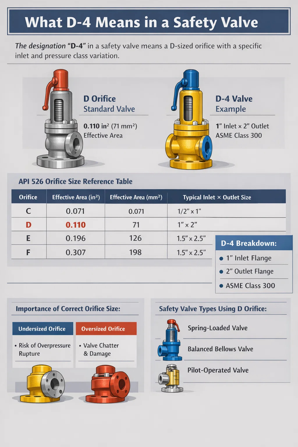
In the context of a safety valve, D-4 refers to a specific orifice designation defined by ASME (American Society of Mechanical Engineers) standards, particularly under ASME Section I and Section VIII, and further adopted by API Standard 526. The "D" letter identifies the orifice size category, while the "-4" suffix — used in certain manufacturer or API-referenced naming conventions — can indicate a variation or subtype within that orifice class, sometimes reflecting seat bore diameter, inlet size pairing, or a manufacturer-specific model variant within the D orifice range.
The standard D orifice in API 526 has a effective flow area of 0.110 square inches (71 mm²). It sits between the smaller C orifice (0.071 in²) and the larger E orifice (0.196 in²), making it one of the most commonly specified orifice sizes for moderate-flow applications in petrochemical and process industries. When a manufacturer appends "-4" to this designation, it typically denotes a specific inlet flange size or a pressure class variant — for example, a D orifice body with a 1-inch inlet and 2-inch outlet (1×2 configuration) rated to a specific ASME pressure class.
Understanding this designation is critical when selecting, purchasing, or replacing a pressure relief valve (PRV) or safety relief valve (SRV), because an incorrect orifice size directly impacts the valve's ability to relieve pressure fast enough to protect equipment from overpressure events.
The ASME and API Orifice Designation System Explained
To fully understand what D-4 means, you need to understand how orifice designations work across the safety valve industry. The ASME and API standardization framework assigns alphabetical letters to standardized orifice flow areas. These letters run from D through T (with some letters skipped), each representing a progressively larger effective flow area.
API Standard 526 — titled "Flanged Steel Pressure-Relief Valves" — is the primary document that governs orifice sizing and valve configurations for flanged safety valves used in petroleum refineries and related industries. The standard establishes orifice area, body sizes, pressure ratings, and material requirements. Every major safety valve manufacturer — including Emerson (Fisher, Crosby), Curtiss-Wright (Farris), Leser, Spirax Sarco, and Neles — designs their product lines around these API 526 orifice designations to ensure interchangeability.
Standard API 526 Orifice Sizes Reference Table
| Orifice Designation | Effective Area (in²) | Effective Area (mm²) | Typical Inlet × Outlet Size |
|---|---|---|---|
| D | 0.110 | 71 | 1" × 2" |
| E | 0.196 | 126 | 1.5" × 2.5" |
| F | 0.307 | 198 | 1.5" × 2.5" |
| G | 0.503 | 324 | 2" × 3" |
| H | 0.785 | 506 | 2" × 3" |
| J | 1.287 | 830 | 3" × 4" |
| K | 1.838 | 1186 | 3" × 4" |
| L | 2.853 | 1841 | 4" × 6" |
The numeric suffix (such as "-4") that sometimes follows the orifice letter in manufacturer catalogs does not originate from API 526 itself. Instead, it reflects manufacturer-specific coding for pressure class, inlet/outlet flange rating, or model generation. For example, some manufacturers use a suffix to indicate that the valve body is rated to ASME Class 300 flanges rather than Class 150 — a distinction that matters enormously at higher operating pressures. Others use it to differentiate a conventional safety valve from a balanced bellows or pilot-operated version within the same orifice family.
How Orifice Size Directly Affects Safety Valve Performance
The orifice is the single most performance-defining component inside a safety valve. It is the narrowest point through which relieving fluid must pass, and its area dictates the maximum flow rate the valve can discharge at a given pressure differential. Selecting the wrong orifice — whether too small or unnecessarily large — creates serious operational and safety consequences.
Undersized Orifice: The Overpressure Risk
If an orifice is too small for the required relieving capacity, the safety valve cannot discharge fluid fast enough when an overpressure event occurs. The system pressure will continue to rise beyond the allowable accumulation limit. Under ASME Section VIII, the maximum allowable accumulation for a single pressure relief valve protecting a pressure vessel is 10% above the maximum allowable working pressure (MAWP) for non-fire cases, and 21% for fire cases. If the valve's orifice cannot handle the required flow within that accumulation band, the vessel is at risk of rupture, which can be catastrophic — releasing toxic, flammable, or high-pressure fluids into the environment.
Oversized Orifice: Chatter and Instability
An orifice that is significantly larger than needed causes a different but equally serious problem: chatter. When the operating pressure is close to the set pressure but the required flow is much less than the valve's rated capacity, the valve opens briefly, releases a small burst of fluid, loses disk lift, snaps shut, and immediately cycles open again. This rapid hammering — sometimes occurring dozens of times per minute — rapidly erodes the valve seat and disk. A chattering safety valve can be destroyed within hours, and it will leak continuously once the seating surfaces are damaged. The D orifice size is specifically appropriate when the calculated required relieving capacity falls within its range — not simply because it is a common size.
Flow Capacity Formula for Safety Valves
For gas and vapor service, the required orifice area is calculated using the following ASME/API formula:
- A = W / (C × K × P₁ × √(M / T × Z))
- Where A = required effective discharge area (in²)
- W = required relieving capacity (lb/hr)
- C = gas constant based on ratio of specific heats
- K = coefficient of discharge (typically 0.975 for certified valves)
- P₁ = relieving pressure in psia (set pressure × 1.1 + 14.7 for 10% accumulation)
- M = molecular weight of gas, T = absolute temperature (°R), Z = compressibility factor
Once the required area is calculated, the engineer selects the next standard API orifice size that is equal to or greater than the calculated area. If the calculation yields a required area of 0.095 in², the D orifice (0.110 in²) would be the correct selection. If the calculation yields 0.115 in², the D orifice is insufficient and the E orifice (0.196 in²) must be selected.
Types of Safety Valves That Use the D Orifice
The D orifice designation applies across multiple safety valve types, each designed for different service conditions. Understanding which valve type is appropriate for your application is as important as selecting the correct orifice size.
Conventional Spring-Loaded Safety Valves
The most widely used design, these valves rely on a spring to hold the disk against the seat until system pressure forces the disk open. A D orifice conventional safety valve is commonly specified for steam service on boilers, compressed air systems, and gas processing equipment with relatively stable backpressure (below 10% of set pressure). The spring force is calibrated to the set pressure; once the inlet pressure reaches the set point, the disk lifts and fluid flows through the D orifice opening. The Emerson Crosby Series 900 and the Farris 2600 Series are well-known examples manufactured with D orifice configurations.
Balanced Bellows Safety Valves
These valves incorporate a bellows assembly that isolates the spring from the outlet side, making the set pressure independent of backpressure. A D orifice balanced bellows valve is appropriate when superimposed or built-up backpressure exceeds 10% of the set pressure — for example, in flare headers where multiple valves discharge into a common header. Without the bellows, variable backpressure would cause the set point to drift, potentially preventing the valve from opening at the correct pressure or causing it to open prematurely.
Pilot-Operated Pressure Relief Valves
Pilot-operated valves use a small pilot valve to sense system pressure and control a larger main valve. They can operate at up to 98% of set pressure without leakage — compared to roughly 90–92% for spring-loaded valves — making them ideal for systems that operate close to their design limits. The D orifice size is less common in pilot-operated valves since these designs are generally preferred for larger flow applications, but they are available for applications requiring tight shutoff combined with precise set pressure control in smaller flow streams.
D Orifice Safety Valve Applications in Industry
The D orifice is one of the smallest flanged safety valve orifices in the API 526 standard, which positions it for specific application niches where flow requirements are moderate but reliability and code compliance are non-negotiable.
- Boiler steam drums: Small package boilers producing steam at pressures between 15 and 250 psig frequently use D orifice safety valves. At these pressures and typical boiler capacities of 2,000–10,000 lb/hr steam, the D orifice provides adequate relieving capacity without over-specification.
- Heat exchangers: Shell-and-tube heat exchangers in chemical plants often require thermal relief protection. The D orifice is well suited for liquid thermal relief scenarios where the required flow is small but a certified, flanged valve is necessary for code compliance under ASME Section VIII.
- Compressed air systems: Air compressor receivers and distribution headers in industrial facilities with operating pressures from 100 to 300 psig commonly specify D orifice safety valves due to the moderate flow requirements relative to the vessel volume.
- Gas processing equipment: Separators, scrubbers, and flash drums in upstream oil and gas operations may require D orifice pressure relief valves when gas flow rates at relieving conditions fall within the 0.110 in² capacity range.
- Pharmaceutical and food processing vessels: Small reactors and storage vessels in these industries often operate under strict hygiene requirements combined with moderate pressure limits, making the D orifice an appropriate flanged safety valve choice.
Manufacturer-Specific Interpretations of D-4 in Safety Valves
While API 526 standardizes the orifice letter, the numeric suffix varies by manufacturer. Here is how several major safety valve manufacturers use a numeric suffix alongside the D orifice designation:
Crosby (Emerson)
Crosby's JOS-E and JBS-E series use the API orifice letter in the model number string. A valve ordered as a "1-D-2" configuration specifies a 1-inch inlet, D orifice, and 2-inch outlet. Crosby does not use a numeric suffix after the orifice letter in the same way as D-4; instead, the numeric elements refer to body connection sizes within their model number structure.
Farris Engineering (Curtiss-Wright)
Farris uses a series number (such as 2600, 2700) combined with an orifice designation. Their ordering codes include the orifice letter separately from a series suffix, but some documentation references combined codes where the number following the orifice letter indicates the spring case or pressure range setting group. In this context, "D4" could reference a D orifice valve configured for a specific spring range group number 4.
Leser
Leser, a German manufacturer with a strong global presence, uses the API orifice letters in their flanged valve series (Type 441, 459, 526) but structures their full model codes differently. A suffix number in their system typically corresponds to a body material group or pressure class — Class 150 versus Class 300 flanges, for instance. A "D-4" notation from Leser documentation would require cross-referencing their specific product catalog to confirm whether the "-4" refers to a material group, pressure class, or service configuration.
Spirax Sarco
Spirax Sarco focuses heavily on steam and condensate applications. Their flanged safety valves for steam service use API orifice designations in certain product lines, with numeric modifiers indicating pressure ratings or trim configurations. When reviewing any Spirax Sarco documentation with a D-4 reference, the "-4" most likely denotes a specific set pressure range bracket within the D orifice body size.
The key takeaway is this: always consult the specific manufacturer's datasheet or ordering guide when you encounter a designation like D-4. The API letter standardizes the flow area. The numeric suffix is proprietary and varies across manufacturers. Ordering a safety valve based solely on a code without verifying manufacturer-specific meaning can result in receiving a valve with incorrect pressure class, trim material, or configuration for your application.
Safety Valve Sizing: Step-by-Step Process for D Orifice Selection
Proper safety valve sizing is a formal engineering process governed by ASME and API codes. It involves several sequential steps, and rushing through them or skipping verification steps is a common cause of field problems.
- Identify the relieving scenario: Determine which overpressure scenario governs — blocked outlet, fire case, utility failure, control valve failure, thermal expansion, or another cause. Each scenario produces a different required relieving rate.
- Calculate required relieving capacity: Based on the governing scenario, calculate the mass flow rate or volumetric flow rate of fluid that must be relieved. For a blocked outlet scenario on a gas system, this is typically the maximum inlet flow rate. For a fire case on a liquid-filled vessel, the calculation follows API 521 heat input formulas based on wetted surface area.
- Determine relieving conditions: Identify the fluid composition, temperature at relieving conditions, inlet pressure (set pressure plus applicable accumulation), and backpressure on the outlet. These parameters feed directly into the orifice area calculation.
- Calculate required orifice area: Apply the appropriate API/ASME formula (gas, steam, or liquid service equations differ). This gives you the minimum required effective flow area in square inches or mm².
- Select next-larger standard orifice: Compare the calculated required area to the API 526 orifice table and select the next available size that exceeds the requirement. If the calculated area is 0.095 in², the D orifice (0.110 in²) is selected. If it is 0.112 in², move up to the E orifice (0.196 in²).
- Verify backpressure compatibility: Confirm that the selected valve type (conventional, balanced bellows, or pilot-operated) is appropriate for the anticipated backpressure level.
- Specify full valve configuration: Determine inlet and outlet flange ratings (ASME Class 150, 300, 600, etc.), body and trim material (carbon steel, stainless steel, alloy), cap style (open or closed), and any special requirements such as soft seats or test gags.
Common Mistakes When Specifying a D Orifice Safety Valve
Even experienced engineers make errors during safety valve specification. The following mistakes appear repeatedly across industry inspections and post-incident reviews involving D orifice and other standard orifice safety valves.
- Using rated capacity instead of required capacity: Safety valve datasheets list the actual rated flow through the valve at the specified conditions. Engineers sometimes match this number to the system's normal operating flow rather than the required relieving flow at overpressure conditions. The relieving scenario — not normal operating conditions — drives the required capacity.
- Ignoring backpressure: Installing a conventional spring-loaded D orifice safety valve on a header where backpressure varies between 15% and 40% of set pressure will cause significant set pressure drift. Balanced bellows or pilot-operated valves must be used in high-backpressure applications.
- Confusing orifice area with bore diameter: The "D" designation refers to the effective discharge area, which accounts for the coefficient of discharge (Kd). The actual physical orifice diameter is larger than the equivalent area calculated from the effective area. Do not substitute physical bore measurements for the effective area in sizing calculations.
- Replacing with a different manufacturer without verifying equivalence: A D orifice valve from Manufacturer A and a D orifice valve from Manufacturer B have the same effective flow area (0.110 in²), but their physical dimensions, spring ranges, material options, and numeric model suffixes may differ. Always verify with the manufacturer before cross-referencing part numbers.
- Setting pressure too close to operating pressure: Safety valves should typically be set at least 10% above the normal operating pressure to prevent simmer and seat damage. A D orifice valve set at 100 psig on a system that routinely operates at 97 psig will suffer accelerated seat wear and may fail to reseat tightly after relieving.
Maintenance and Testing Requirements for D Orifice Safety Valves
A properly sized and installed D orifice safety valve still requires regular maintenance and testing to remain functional and code-compliant. Jurisdictional requirements for safety valve testing intervals vary, but most regulatory frameworks and industry best practices align with the following guidelines.
Testing Intervals
The National Board of Boiler and Pressure Vessel Inspectors (NB-23) and most state jurisdictions in the United States require safety valves on boilers to be tested at least annually. For pressure vessels under ASME Section VIII, testing intervals are often governed by the owner's risk-based inspection (RBI) program, which may specify intervals of 2–5 years depending on service severity and valve history. API 576 — "Inspection of Pressure-Relieving Devices" — provides detailed guidance on inspection intervals, testing methods, and acceptance criteria for pressure relief valves including D orifice configurations.
Bench Testing vs. In-Place Testing
Safety valves can be tested in place using a test lift lever (where provided and where system pressure is sufficient) or on a test bench after removal from service. Bench testing is more comprehensive and is required when the valve must be recertified after repair or when in-place testing cannot verify set pressure accurately. During bench testing, a D orifice safety valve is subjected to increasing inlet pressure until it pops open; the set pressure is verified, and the valve is inspected for seat tightness after reseating.
Common Maintenance Issues
- Seat leakage: The most common problem found during inspection. Caused by process contamination on the seat, chatter damage, or corrosion. The D orifice, being a small valve, is particularly susceptible to particle contamination blocking the seat.
- Spring fatigue or corrosion: Springs lose tension over time, particularly in high-temperature or corrosive service. A fatigued spring will cause the set pressure to drift downward.
- Inlet blockage: Debris accumulation at the inlet restricts flow through the D orifice and can prevent the valve from reaching full lift. Inlet screens, where used, must be regularly cleaned.
- Outlet backpressure buildup: Partially blocked discharge piping increases backpressure and affects set pressure and relieving capacity for conventional (non-balanced) safety valves.
Regulatory Standards Governing Safety Valves with D Orifice Designation
Safety valves — including those with D and D-4 orifice designations — must comply with a layered set of codes and standards. Understanding which standards apply to your specific installation is essential for legal compliance and safe operation.
- ASME Section I: Covers power boilers. Safety valves on boilers must be ASME-certified and stamped with the "V" code symbol, indicating they have passed capacity certification testing at a recognized testing laboratory.
- ASME Section VIII: Covers pressure vessels. Pressure relief valves must carry the "UV" stamp for pressure relief valves or "UD" stamp for rupture disks. The D orifice is commonly used in Section VIII applications.
- API Standard 526: Establishes dimensional and material standards for flanged steel pressure relief valves used in petroleum and chemical industries. Defines the D orifice effective area as 0.110 in².
- API Standard 520 (Parts I and II): Provides sizing, selection, and installation guidance for pressure-relieving devices. Part I covers design and sizing; Part II covers installation requirements including inlet and outlet piping design to prevent chatter and excessive backpressure.
- API Standard 521: Covers pressure-relieving and depressuring systems, including flare and vent system design. Required reading when designing the discharge system for safety valves.
- PED (Pressure Equipment Directive) 2014/68/EU: European equivalent framework governing pressure relief devices, including safety valves used in EU member states.
- National Board Inspection Code (NBIC / NB-23): Governs the installation, inspection, and repair of pressure relief devices in jurisdictions that have adopted it, primarily across the United States and Canada.